Any comp lives or dies on subtle qualities of a scene – color, depth of field, lens distortion, etc etc. Solving lens distortion with nuke is pretty easy once you understand the process (and immensely easy if you prepare ahead of time!); without a good lens distortion solve you’ll never get a convincing composite. Depth of field is easier to do a guess-and-check method, but of course we’d much rather get an accurate result. We’ll discuss both, but first a quick overview of the technodolly itself.
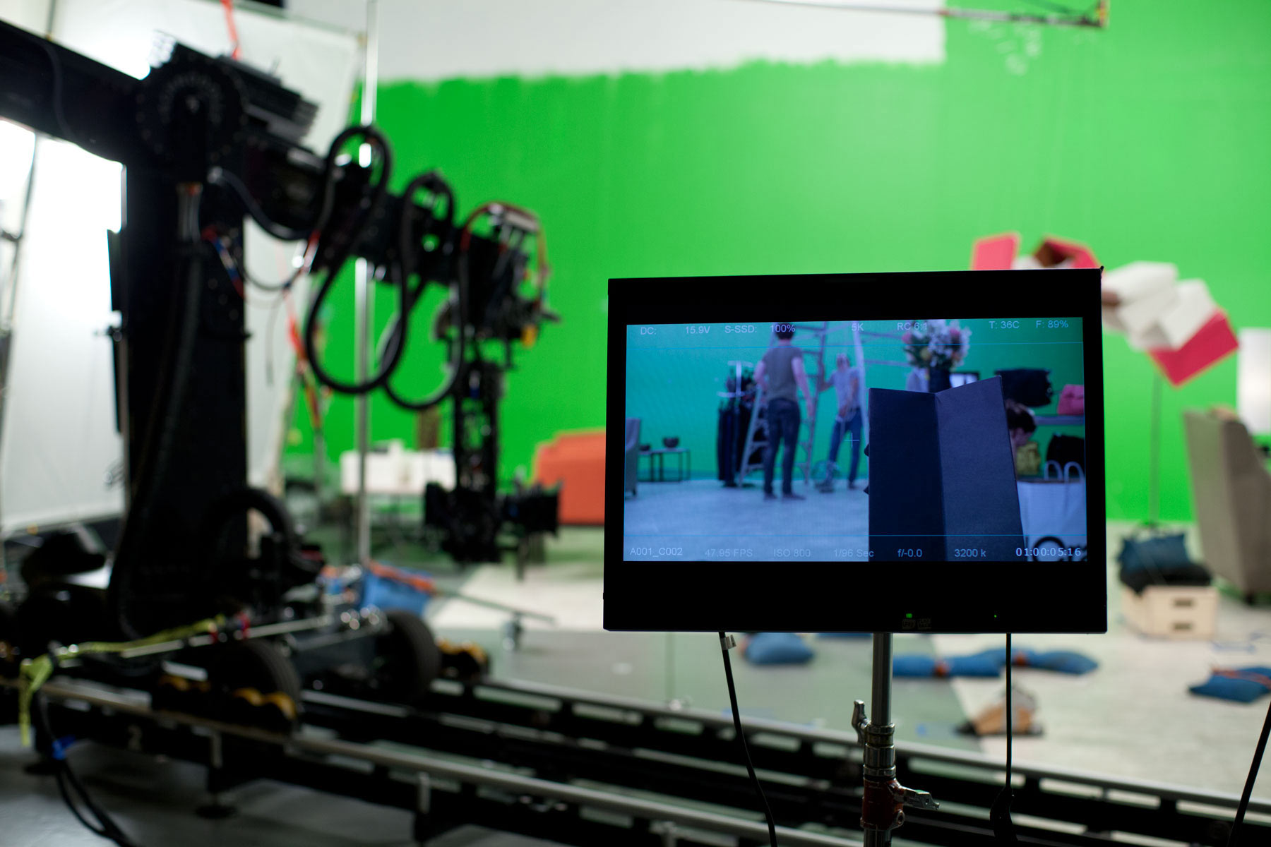
The technodolly is an established player in the motion control scene – the high-end workhorse that’s accessible to all of us who aren’t working on cutting edge equipment at WETA or the like. A qualified technician will work with the director and program in a “move” that can be repeated many times, allowing complicated shots to be closely controlled, and for the creation of multiple “passes” to be overlaid in compositing1. Depending on your facility, you may be provided with an FBX or the raw data (in a comma-separated values file with a .cgi extension). For these tasks, we’re going to look at the raw data, since the FBX will discard the focus info.
| R0.00 | -3.0081 | 0.9409 | 0.1832 | -89.379 | -89.944 | 0.000 | 0.000 | 99.786 | 0.000 |
| R1.00 | -3.0081 | 0.9409 | 0.1832 | -89.379 | -89.944 | 0.000 | 0.000 | 99.786 | 0.000 |
…
| R480.00 | -2.9630 | 1.1190 | 2.5815 | -89.886 | -89.961 | 0.000 | 0.000 | 12.368 | 0.000 |
According to the Technodolly Export Manual, the columns are (in order):
- frame number (leading ‘R’)
- X
- Y
- Z
- pan
- tilt
- roll
- zoom
- focus
- iris
In this case, the technodolly was not connected to the camera’s iris or zoom, so they are zero. For our lens distortion/depth of field calculations, we’re going to use the lens2 number.
On set, we prepared a shot specifically for calculating lens distortion as well as some information for focus. We laid out a large-scale lens distortion chart3 on the floor, and programmed a move that started fully zoomed in, and pulled up as far as we could in the space. This provided us with a lens distortion chart image for all (well, most) planes of focus relative to the lens4. Here you can see the video of the lens distortion move:
In Nuke, we ran the lens distortion removal gizmo at both the beginning and the end, and determined that the difference was minimal if at all, so we simply used one set of corrections for all focal planes. Needless to say, this was easier than having to change them on the fly.
On set, we measured the distance between the chart and the film plane/sensor (on the red, there is an icon on the housing indicating where the sensor is) at the beginning of the move (12″) and at the end (106″). This number, combined with the “lens” value from the CGI file, should be enough to help us determine the focal plane at any point during the shot. Here’s the two important values side-by-side:
| Distance | Focus |
| 0.1832 | 99.786 |
| 2.5815 | 12.368 |
As you can see, while the distance to the focal plane gets larger, the arbitrary “lens” value gets smaller. However, if we plot these points with Grapher we can see that the relationship is not linear:
man, that’s a lot of arbitrary numbers!
At every point during our shot, what we’ll have is the arbitrary “lens” value (0-100), and what we’ll need is the distance to the focal point in the scene, so what we need to do is make an equation that will convert “lens” to distance. If we want, we can first convert those distance numbers to something physical (we know that the total distance travelled in this move is 106″) but for now we’ll create our equation using these 3D units, as we’ll most likely be generating a depth map in our 3D application.
I wish I could say that there was some mathemagical/computational way to come up with an equation for this curve, but as far as I know there isn’t. So with a lot of guess-and-check work in the grapher, I came up with this equation:
y=(-tanh(((x-13)*8)/100)*1.9)+2.0832+(100-x)/300| Distance | Focus | Est. Distance |
| 0.1832 | 99.786 | 0.1839 |
| 2.5815 | 12.368 | 2.4712 |
Not bad! Now, our equation is going to get more inaccurate as the values of “focus” get lower, but as that is happening while the focus is going towards infinity, it shouldn’t be much of an issue.
- It should be noted that your passes are never going to be EXACTLY the same. There’s always going to be some small amount of shudder that’s going to make your passes slightly off, so you should be prepared to do some correction for this [↩]
- The technodolly has a gear on the side that can manually turn the focus on the camera. This number is not directly related to the focus settings on the camera, but rather represents the arbitrary amount of rotation of this gear. [↩]
- hat-tip Eric Alba [↩]
- There is often a large amount of change or “breathing” in the lens when the focus/zoom would shift, which would mean the distortion could be different at different focal planes. In this case, with the Red camera and modern lenses, there was no noticeable change in our levels of focus, but it was better to be prepared than to be surprised! [↩]

